Blog
Kitchen Design Plugin for Sketchup, Sketchup training.
Handibot Sharpie Mod
Being that the high temperature around me has been in the single digits for a few days I decided to find something that didn't involve working in an unheated garage. Teaching people how to use a CNC can be a loud and dusty experience. I've always thought it would be better to have people draw with a CNC first before making any sawdust. It's easier, safer, and quiet.
Read MoreTerrain Models
Just the other day I wanted to 3D print, and CNC mill some terrain out onto different materials. The idea here is to use Sketchup to create the terrain, and then send it out to different tools to make the terrain. The vision is to have the CNC mill make large swaths of terrain on foam or wood, and then use the 3D printer for small things like buildings.
To do this effectively I wanted to be able to use Sketchup. Sketchup allows for easy scaling of objects, and also has the "sandbox" tools that allow for roads and buildings to be stamped into terrain.
Challenge 1: Getting terrain models into Sketchup
This was not as easy as I thought it would be. For several versions now Sketchup has had the ability to import Google Earth terrain. While this does work, and you can mill it, you are only allowed to bring in very small plots at one time. This can make it nearly impossible to do a whole mountain at once. Even a state as small as Massachusetts could require 50 imports. I wanted a better way...
Sketchup has a little known importer called DEM. DEM stands for "Digital Elevation Data"
“The 7.5-minute Digital Elevation Model (DEM) data files are digital representations of cartographic information in a raster form.”

The DEM files can be easily downloaded from this website.

Before you complete the import, click on options:

Set your "points" for import to 9,999. if you don't, the default will be a very bumpy terrain import.
Once you've imported your model, you'll get something that looks like this. This may look a little flat, we can fix that using the Scale tool in Sketchup. Click once to highlight your terrain, and click the Scale tool.

You can see when you scale it vertically you get much more definition in the terrain. A scale factor of 4 can be seen here.
You may notice that Sophie, who is life sized in Sketchup is really small now. That's because this terrain comes into Sketchup full scale. For our purposes here we're going to want to scale this down, a lot. If you bring this into Aspire or MakerWare it's going to be so huge it may be difficult to figure out what's going on. Thankfully this is really easy in Sketchup.
Double click your terrain to enter it's group. Once you do that, click on the tape measure tool and measure from point to point. This terrain is over 35,000 feet on the short side! Once you click for the measurement, just type in how wide you want it to be. In this case I made it 6". You can see after I press enter that the terrain shrinks to a more manageable width.

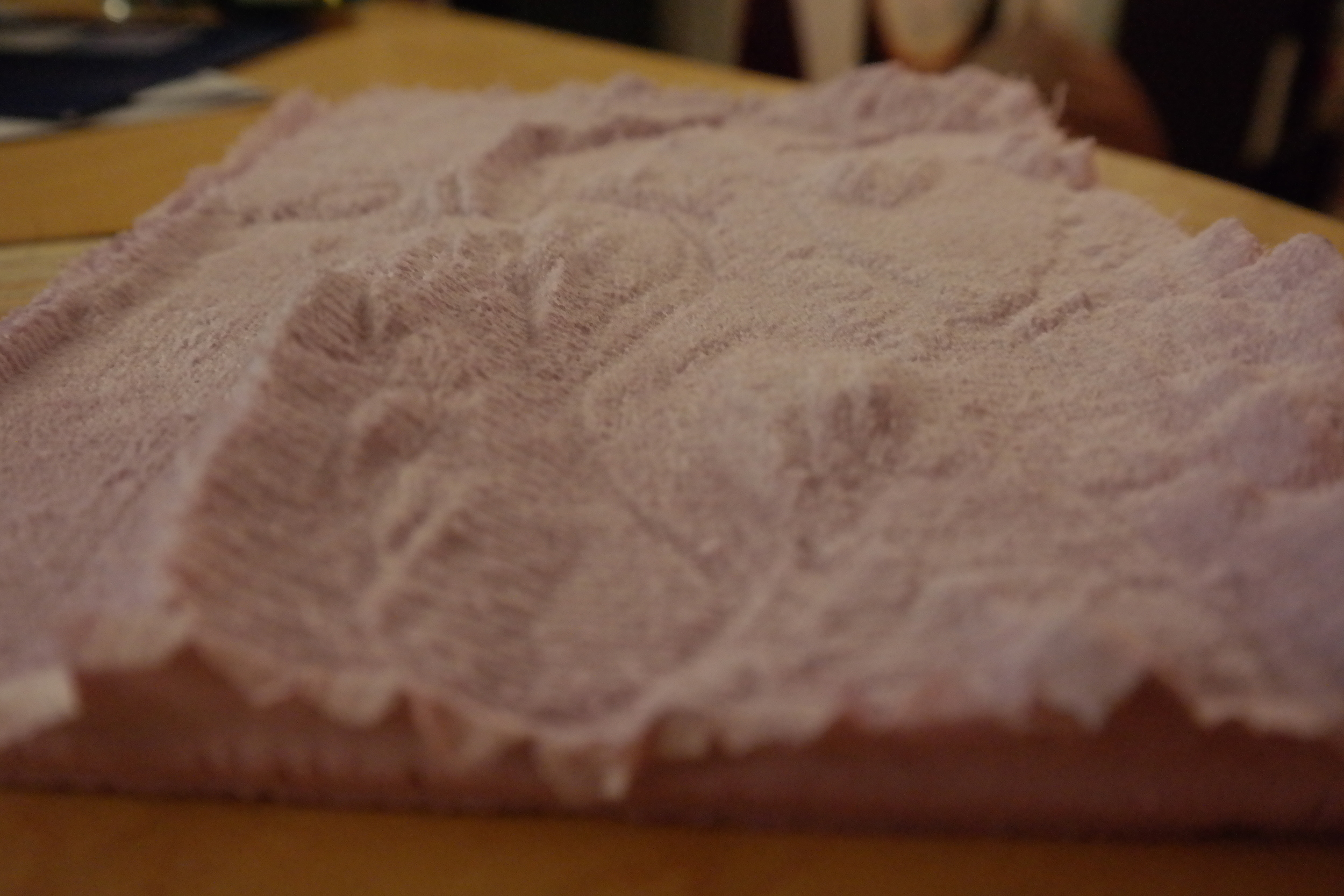
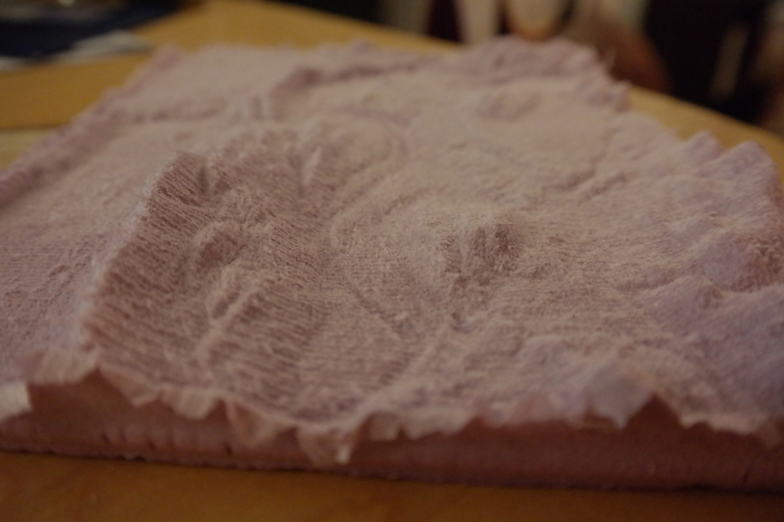
Once you've done the scaling, you can export the terrain to STL. Now you can bring that file into Aspire for CNC milling. (I did mine on the Handibot). You can also bring that same STL into Makerware for 3D printing.
STL Ready for 3D printing
STL ready for CNC milling in Aspire
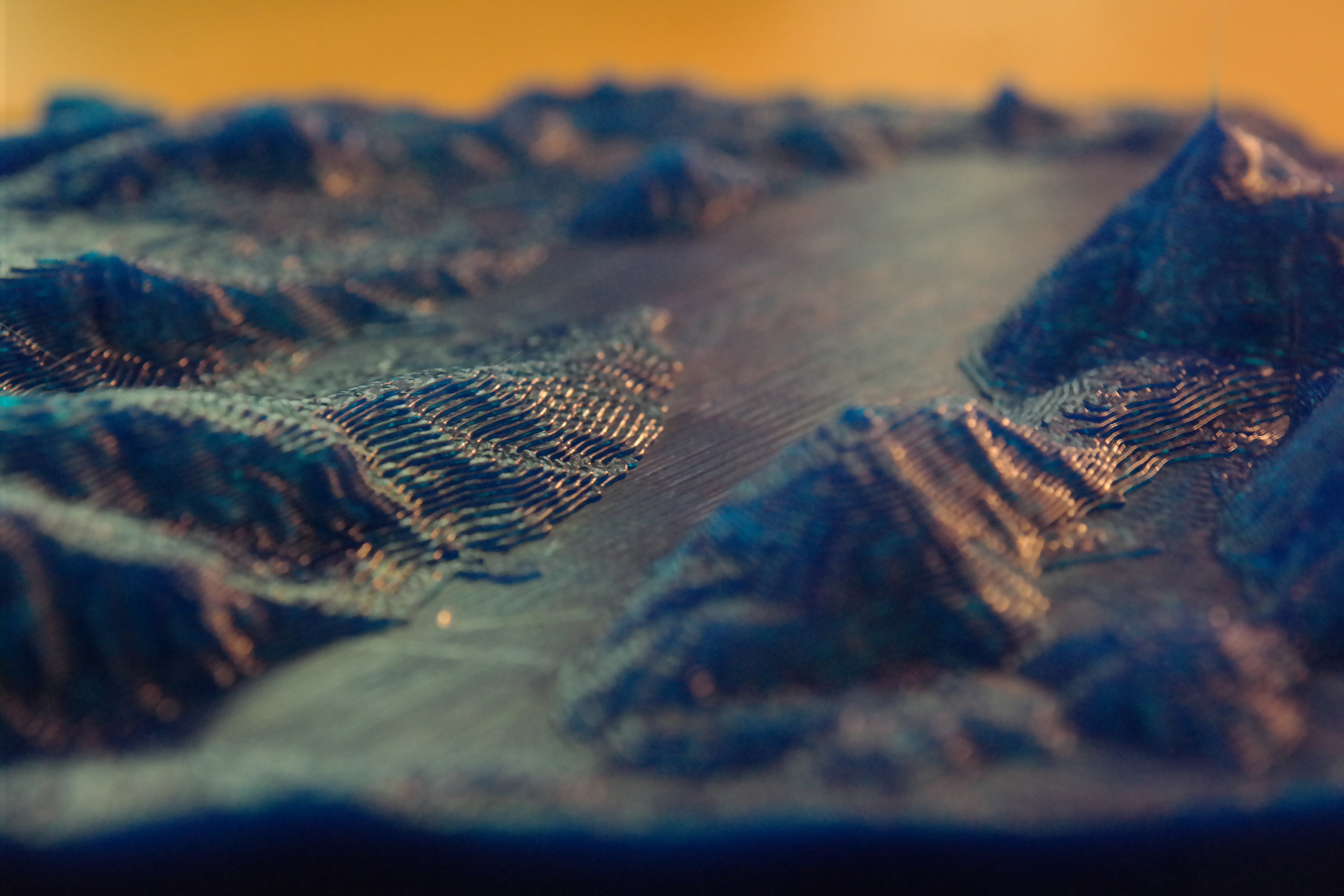
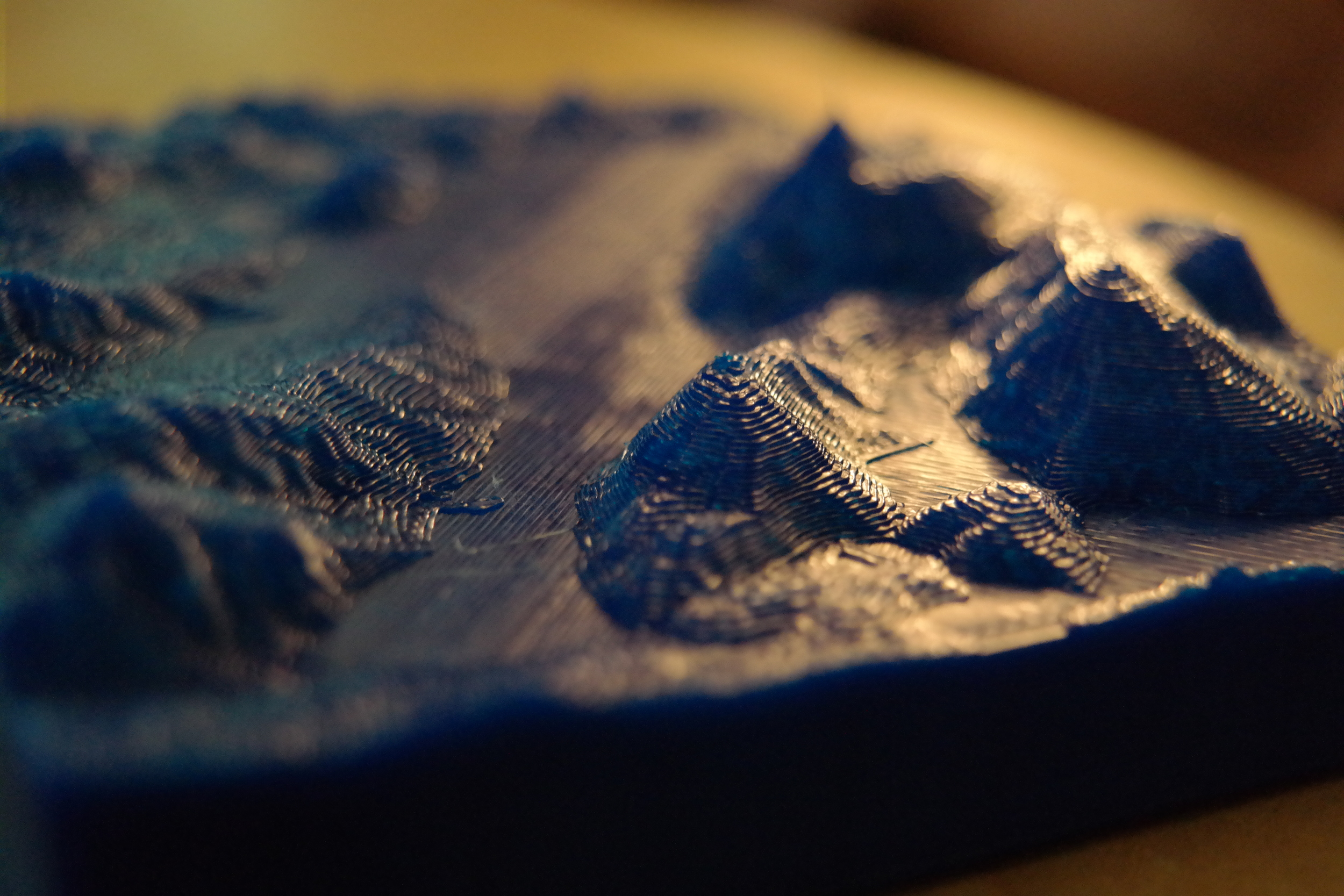
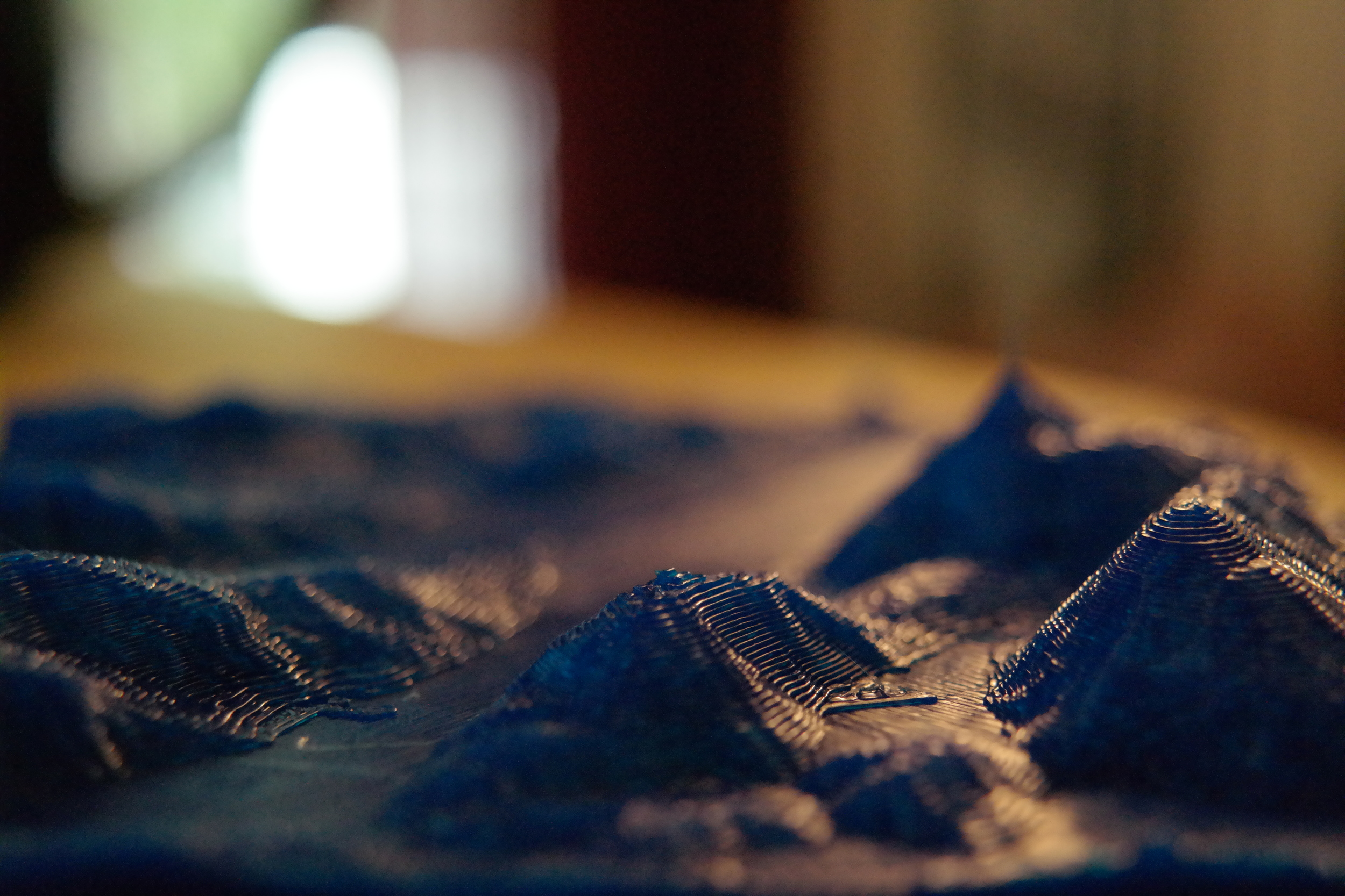
The results? Great! You can see in the gallery below I 3D printed, and CNC milled this section of terrain. Having Sketchup as the nexus for this 3D models is fantastic. I could see an architect or a city planner using this method to print large parts of terrain with a CNC, and then doing buildings and other obstacles with the 3D printer. You could make sure they are all scaled properly using Sketchup.
Some considerations:
The way this works is that you start from a full scale terrain model and you shrink it down and then enhance it's elevation. If you were building a large map, and only had access to smaller CNC machines like a Handibot it would be wise to develop some rules for scaling. If you pick a particular scale factor for both the overall size, and the height enhancement you could mill lots of these "tiles" and stick them together for a huge map. Since the initial dataset (the DEM files) is uniform you could potentially farm this work out to something like 100kGarages and quickly get a huge terrain model done.

Marvin 3D print
Here's a cute little guy I printed the other day. No support material needed!
You can print your own Marvin right here.
PVC Tube Factory
For Maker Faire I was in charge of fabricating a couple of geodesic domes. Because of that I had a few pieces of PVC pipe laying around. I've been experimenting with automating the process of milling things with the Handibot, and milling logos onto pipe seemed like the perfect project. The idea was to get the Handibot to mill logos down a long section of pipe automatically without me having to intervene. The results in this video below should speak for themselves:
If you're looking at the video and wondering how I did it, you're in luck... I'm about to explain the whole thing.
First, you're going to need a few things:
- A Handibot
- Aspire for toolpathing (You can use VCarve if you're not milling on to a 3D model like I was)
- Sketchup for the jig model
- Some 1.5" Schedule 40 PVC
- Free time
- Willingness to experiment
- These files
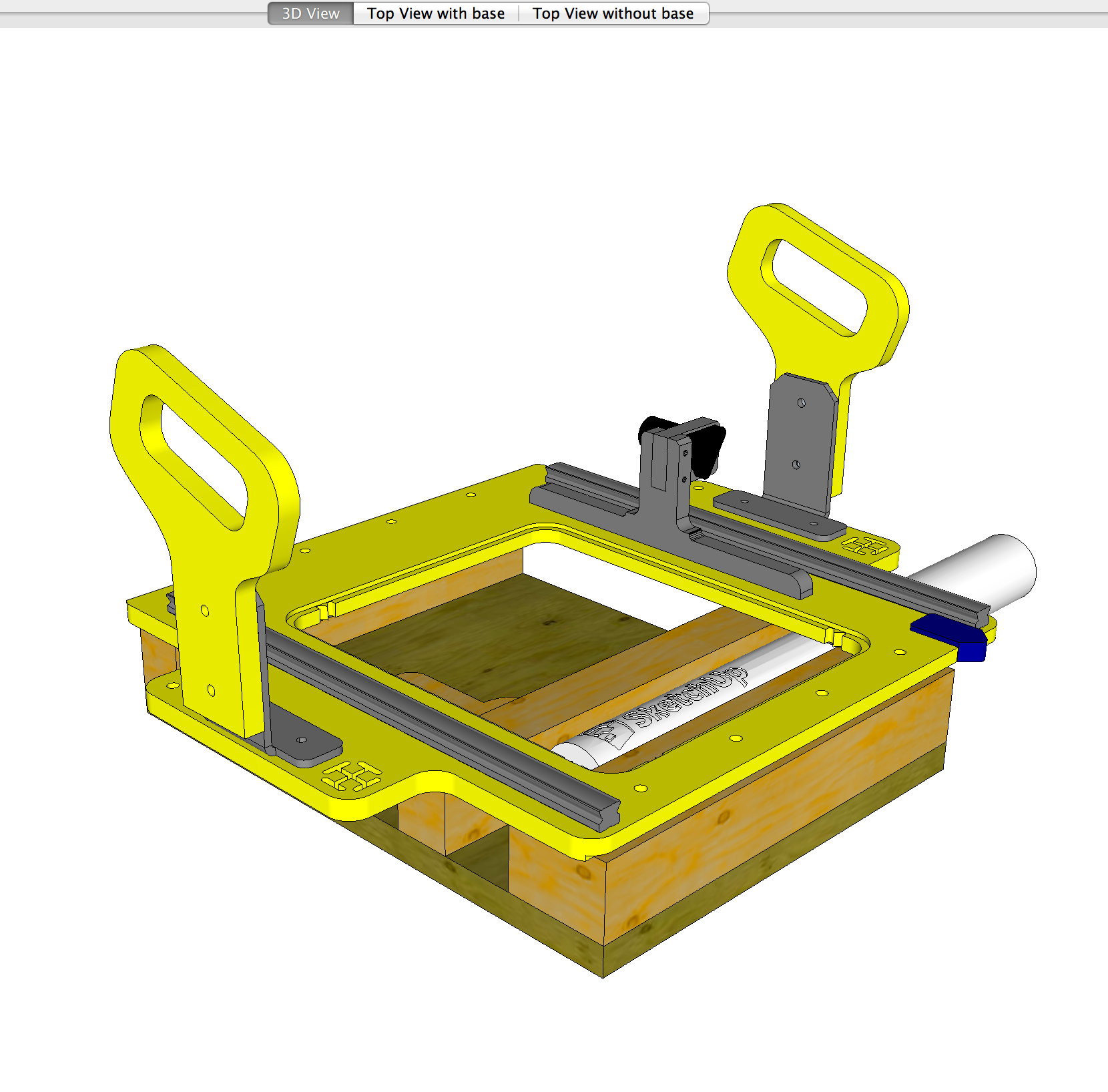
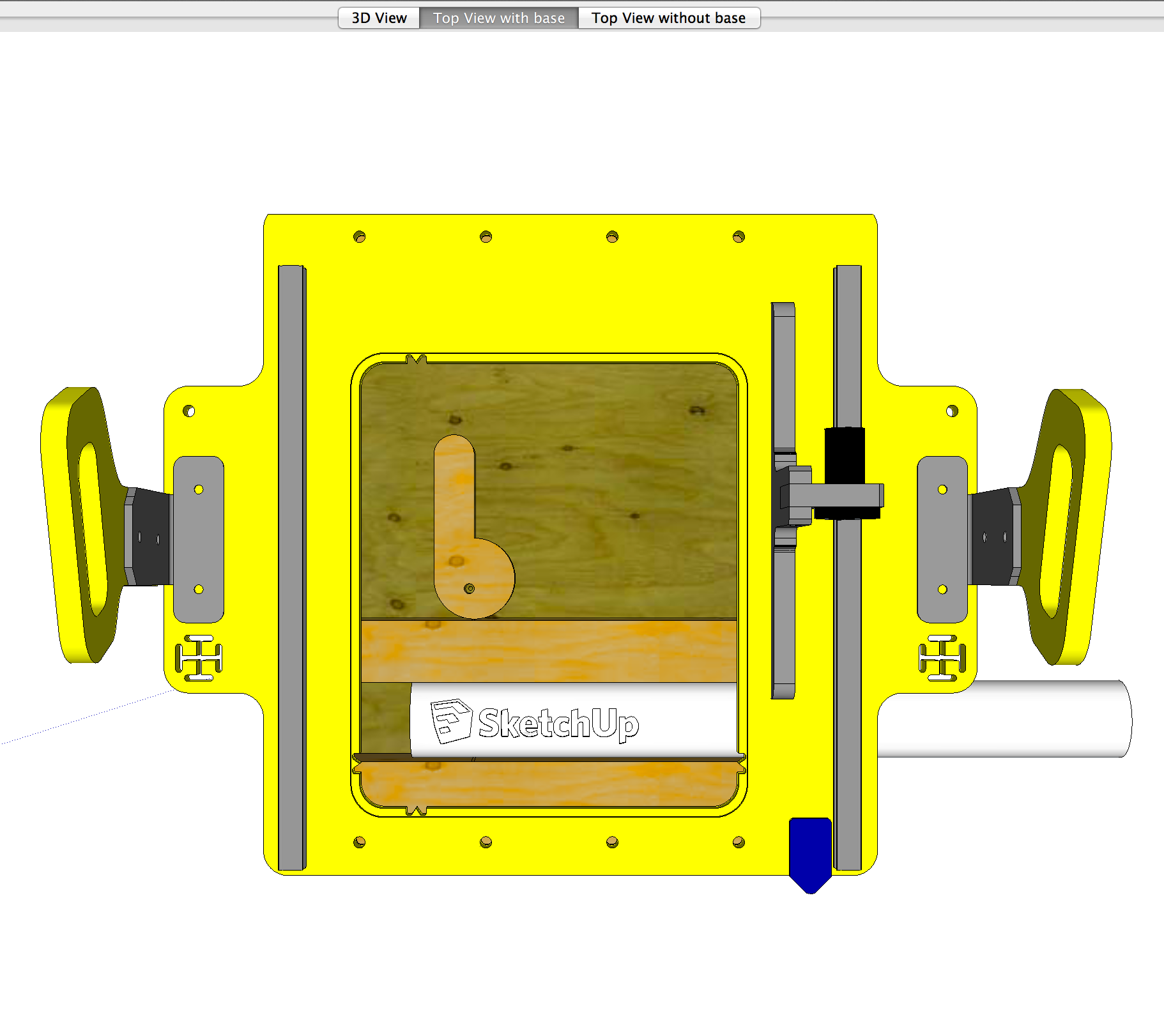
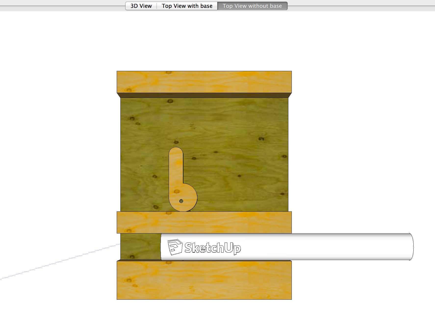
First, open up the Sketchup model. Near the top of the screen you'll see scene tabs that are labeled. Click trough those to get an idea of what the jig looks like. You can use the Tape Measure tool in Sketchup to measure this out to make your own.
Open up the Aspire file that was included in the download. When you get it open you'll see several things going on here....
First, there is a 3D pipe in there at the bottom. That was drawn in Sketchup, exported to STL, and then imported into Aspire. (Those files are in the Sketchup model directory) This allows us to project our carved toolpath onto the pipe's surface.
Next I drew a rectangle in Aspire that represented my scrap 2x4 that would be used to hold the pipe in place when the clamp is drawn down.
After that I drew a clamp in the released, and lock position.
Finally I copied the clamp onto a layer that's currently hidden so I could cut it out of some scrap.
Lastly I setup a toolpath that poked a hole where the clamp should be screwed into.
After you have that done, build the jig just like I have it in the Sketchup model. Place the Handibot onto it and screw it in place.
Then run the "center point" toolpath with a Vbit. That will peck a small hole into your material. This hole will show you where to screw that clamp you milled out of scrap.
After I did all that, I setup toolpaths for all the cuts, and the moves. You'll see in there that there are toolpaths for locking the clamp, unlocking the clamp, milling the logo, and sliding the pipe.
To move the clamps, I needed to move the tool without having the router on. You can accomplish this by manually editing the Shopbot code, but I wanted an easier way. Thankfully Brian from Ventric stepped up (as he usually does) and wrote a custom post processor to use for this project. The way he set this up is to turn off the router if you set your "spindle speed" to between 1 and 99.

This is a special post processor that can be found here. You'll need to copy it into your My Post Processors directory in Aspire. You can find that directory by using this guide. This is required to pull off this trick as you can see that any time I need to move something, in the toolpath I have my spindle speed set to 1. This means that on my Handibot the router won't be running so I can move clamps or slide pipes without turning them to sawdust. If you double click on my toolpaths you'll see that any "move" ones have a spindle speed of 1. That means when I use this custom post processor when those toolpaths are running the router will be off.
I saved the toolpaths out as two different files. One that locks the clamp. It's called "Lock Clamp" and the rest of the moves are called "After Lock Clamp"

You'll see in the script called "Call Actions.sbp" That the "Lock Clamp" action is called first. As you'll see in the video the Handibot will swing down and lock the clamp. Steps are lost because of the pressure that is needed to effectively lock the clamp causes the stepper motors to lose their place. That's why the next action is "XYZero.sbp". This XY action re-zeroes the tool using the proximity switches. This the exact ShopBot code that is used with you use the C3 command except I've removed the prompts, and the tool retracting up on Z. You can see the code differences here from the original. It's only two lines that are changed. I did this because the normal C3 code wants you to press OK when it's done, something that would have stopped the process from happening automatically. Also, since I was so close to the top end of Z, the C3 code pulling up on Z made me lose steps as I was near the physical top of the Z range of the tool.
After the tool is re-zeroed the milling begins. There is one milling pass with the tool on, and one with it off. This removes all the PVC hairs. After that the clamp is released, the pipe is slid over, and the process repeats indefinitely. I was able to let this run for hours without any intervention with a 10' pipe. Afterwards I just chopped off the logos in a chop saw and I was all set!
So there you have it, a totally automated PVC factory using the Handibot. I did this to make PVC pipe souvenirs for Maker Faire. For most people, I think this could be a great way to mill repeating things like circuit boards, or signs using the Handibot. This was an effective and relatively low tech solution. Anyone with a little patience should be able to pull this off with their Handibot.